Riders of Rohan – War Steeds

Some random bullet points, mostly for friends of mine so I can point them at this as a War Steed introduction.

  • You get access to War Steeds by doing the Epic quest in Riders of Rohan.  Volume III, Book 8 to be precise.  You can work through that Epic line as soon as you have access to Rohan, it’s well worth doing, because it has some of the best Epic ‘story’ quests since Moria.
  • You seem to only own a single steed.  It shows up as a mount in the regular Skill | Mount window, near the bottom.
  • When you first get the steed, it’s a Medium war steed.  There are three types, Light, Medium and Heavy.  You are not restricted to any one kind regardless of class, but some might suit certain classes better.
  • The factor which determines whether you have a Light, Medium or Heavy is which Mounted Combat Traits you spend points in.  There are three lines, Light, Medium and Heavy and as soon as you spend your first point, your steed converts to a Light, Medium or Heavy steed (medium seems to be the default).
  • You can reset the points for a few silver, so it’s not a permanent thing, you can switch between different kinds of steeds for different kinds of situations.
  • There’s a new legendary item, Bridles.  Bridles come in three flavours, light, medium and heavy.  You can equip one at a time, they apply their benefits regardless of the type of mount (so a Light Bridle works even if you’re on a Heavy Steed), but obviously, because the traits vary, and the items affect the traits, a Light Bridle will offer more benefit on a Light Steed.
  • Riding the horses is much tougher than travel horses at the start, so they won’t replace them straight away (maybe ever).
  • Your steed has armour and morale, and damage is absorbed by the steed during combat protecting you to some extent.
  • All classes get a new set of mounted combat skills (must be purchased), you don’t fight using your own regular class skills.
  • Steeds earn experience and level up, allowing you to spend more points on traits.
  • Quests offer XP, Legendary Item XP and now Steed XP.
  • You appear to earn Steed XP from kills even while not mounted, but at a reduced rate.
  • Mounted, Steed XP is equal to Item XP from kills, unmounted it appears to be worth around 1/3 that of item XP per kill.
  • Steed XP appears to be earned on all kills, not just quest related kills.

The BT / above.net thing, part 2

So the issue with routing between BT and above.net made The Register, and finally got a mention on the BT Status page.  Lo and behold, this evening, everything seems a lot better.

If only BT had taken the issue seriously on Friday, or maybe, you know, perhaps have even detected it on their own network with their own monitoring, and resolved it themselves, they would have had a bunch of people feeling much happier.

BT & Above.net broken

So the network routing between BT and Above.net has been broken since Friday.  The problem only really manifests at around 7pm when packet loss through that route climbs to unacceptable levels (like 80%+).  It varies all the way through to about midnight by which time it’s down to 1-10% loss and services are usable.

It’s affecting access to Twitter, EA games, Eve Online and anything else which goes via that route.  Access to other web services are entirely unaffected.  To anyone who knows how to use traceroute it’s obvious where the problem lies.

Yet it’s been impossible to get BT to accept there is an issue or demonstrate they’re really investigating.  The @BTCare account on Twitter tells us they are, but no evidence.  The status page says something about ‘upgrades to the network’ but that only showed up at 8pm last night.  My fault report last night has been marked as ‘cleared’ probably because the problem went away, as normal, at around midnight.

Come on BT, take some notice – do something.  These two threads show the extent of the problem,

There’s plenty of traceroutes in them showing the issue between BT and Above.net – speak to each other, work it out, fix it permanently.   Everyone in those threads is fully expecting the issue to come back tonight.

A bit of a Sinclair roundup

I haven’t touched the Spectrums for a few days, the blog posts over the last couple of day were written at the start of the week and then just auto-published each day.  Today though I’ve got plenty of time on my hands and thought it was time I took stock, literally.  By the time I wrote this blog post, I had 5 Sinclair ZX Spectrums in the house.

Pretty worrying, considering I only discovered my desire to own one around the second week in September 2012.  It’s now only just nearing the end of the first week in October.  Those five have ballooned to seven!  Well okay, perhaps not ballooned.  I bought another two rubber key 48K speccies, one which was for parts only for a few quid and another which was on buy now, no postage charges, and was described as in working order, which felt like a bargain (£15 is the minimum I’d expect to see a known working Spectrum go for, before postage, on eBay).

In those 3 or 4 weeks, I’ve built a cable, bought a second hand portable TV, discovered how to load games from MP3, replaced a keyboard membrane, and generally immersed myself in the retro world of Sinclair computers.  So I thought it was time to finally review what I’ve actually ended up owning.  At the same time, I wanted to record some details of the Spectrums, because there’s a guy who is collating a list of known Spectrum serial numbers (no one’s sure if they mean anything) over at World of Spectrum, and I wanted to send him the info for mine.

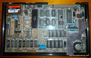
I also wanted some better photographs of the contents of the machines, and I’m going to revamp the Retro Computing page with a sub-page for each microcomputer.

So yes, we’re up to 7, and here they are listed by serial number (not in any order),

001-233295 (48K)

£15 – sold as ‘working’ but in fact, doesn’t. Keyboard not connected, and output is solid black / crawling black square.

001-430610 (48K)

£17 (box, power supply) – sold as working, but keyboard membrane was broken. Now repaired, otherwise very good condition.

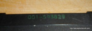
001-593829 (48K)

£9.38 – excellent condition

023-026860 (16K)

£3.70 – case is scratched, but otherwise okay condition

D01-225177 (48K)

£7.50 (including printer, dK’tronics interface, 2 joysticks) – case is in bad condition, rest is fine.

D01-387238 (Not sure of memory size)

£3.53 – bought non-working as parts, no viable display output and case is in terrible condition.

U-075778 (128K Grey +2)

£0.99 – bought in unknown condition, UHF modulator looks damaged, composite output from 8pin DIN is dirty but usable.

Reading back, I think it’s safe to say that with retro computers from 30 years ago, you do not get what you pay for and buyer should always beware!  I’m happy overall with the pile of stuff I have so far (I haven’t listed the random peripherals and power supplies), but if I’d been trying to just buy one working Spectrum on a budget, I would have been disappointed (I’m sure the ~£50 boxed ones work fine – probably).

DIN plugs and phono sockets and all things nice

Some people spend a lot of time when they’re young making things. I spent quite a lot of time unmaking things, but I never got around to putting them back together again. I melted plastic solders, burned airfix aircraft (after building them to be fair), took apart a radio that I remember, and generally ended up with a lot of parts.  By the time I left school and went to University I was heavily into writing software and understanding computers, but not electronics.  As I’ve said, one of the main reasons for getting some old Spectrums is to give myself a reason to do some electronics and electrical stuff.  If you don’t have a reason to do something, then learning how to do it can be very dry, and for me, doing is learning.  One thing I’m terrible at, however, is keeping at something if I don’t immediately get useful results.

I think if you were to describe me in two words it would be easily discouraged.  I have so many half started DIY projects in the house; sort out lighting, cupboards, plumbing, etc.  As soon as it gets hard or as soon as my first attempt doesn’t work, I’m likely to give up.  With the Spectrums I’m trying hard to get over that and to do something even if I fail the first few times.  We’ll see how that works out.
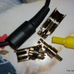
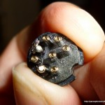
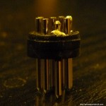
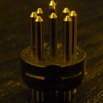
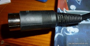
So anyway, the 128K ZX Spectrum +2 with the broken UHF modulator still has a broken UHF modulator.  I tried messing with a bastardised phono lead to see if I could get composite on the TV, and I got enough of a signal to give me some confidence it was being generated.  On the back of that, I bought some cable, a couple of 8 pin DIN plugs and a couple of phono plugs (photo right).  I knew I’d need at least two of each because I was bound the screw up the first attempt.  The phono plugs are the cheap ‘no soldering required’ type, which is good, but the connection won’t last long I should imagine.

The DIN plugs however always need soldering.  After I got the plugs, I read up on how you solder them.  Er, maybe I should have picked something a little easier to start with?  Too late now.  One of the major problems people report with cheap DIN plugs (and these are cheap) is that heating the pins to tin them, or to get the wire in, can melt the plastic.  I already had some metal crocodile clips to use as heat-sinks for heat sensitive soldering, so I was hoping they would be good enough to draw the heat away from the plastic.  I bought shielded 4-core wire, just because I knew this cable might be temporary and once I cut the ends off, I might want it for something else.  The first decision was, do I use 1 wire for ground and 1 for the signal, or do I use the shielding for ground, and just 1 wire for the signal?  I dunno, I’ve never done this before – I took a gamble and decided to use the shielding for ground.

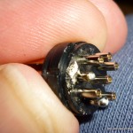
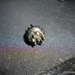
The first job was to tin the signal wire and the shielding (twisted together), and that went pretty well (so well, I took no photos).  But then it was on to the DIN plug itself.  Firstly, the pins are very close together so actually gripping them with the crocodile clip proved difficult.  On top of that, my hands are a bit shaky these days, and I’m nothing like confident with the soldering iron.  The result?  One melted DIN plug connector.
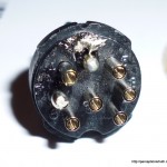
The last two shots show the main issue.  Pushing on the signal pin to heat it up before tinning it, it heats up the plastic, and then just slides forward.  Not to mention catching the plastic with the soldering iron once (hence the splodge of solder on it).  Despite this mess, it did slightly increase my confidence, the ground pin (#2) worked quite well when I got a good grip with the crocodile clip.  Given that, and a deep breath, I took a shot at the second plug.

And it worked.  Feeding the wires into the pins, and soldering them, is pretty fricking tricky, but this is the end result.
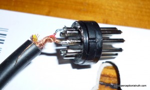
There’s too much wire on show for the signal wire, but hey, not bad for my second ever attempt. With the sheath on, and clamped into place you can’t tell anyway!
I quickly tinned the other end, and screwed / clamped the wires into the phono plug and then checked the result on the portable TV.  It was a little bit disappointing, there’s definitely a signal, but it’s very snowy and loses sync every now and then.  Still, it’s better than it was when I was just pushing wires into the DIN socket.

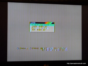
Now that I was happy it wasn’t going to blow the TV up, I tried it on the LCD in the lounge.  Perhaps the portable’s composite input has issues I thought.  Here’s the result.
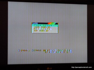
It looks a tiny bit better on the photo than it does on the TV itself, probably because it’s a little bit blurry, but I’m bloody happy!  The Spectrum +2 composite output is notoriously noisy.

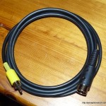
Many of you may laugh when you read this – all I did was solder two wires and turn a couple of screws, but for me, this is a pretty major achievement.  I wasn’t put off when the first plug failed, and I’ve got a cable that actually does what I wanted it to do (first picture in article, top right).  It’s 37 years too late, but I think I may have finally made something my dad would have been proud of.

As I said, the composite on the +2 is terrible, and one of the reasons is because a transistor on the board is mounted the wrong way around.  You can read all about it in this pdf or the word document linked to in this blog post.  So, on the assumption that my dodgy cable is fine, I’m going to have a shot at removing the transistor and putting it back the other way around, and see if that improves the signal.  Having never, in my life, soldered anything onto a PCB, this can only be a simple operation without any risk, can’t it?

I fixed one (or Replacing your ZX Spectrum 48K Keyboard Membrane)

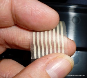
Poor old 001-430610.  It was sold on eBay as fully working 48K ZX Spectrum, but by the time it got to me, the keyboard membrane connectors were so badly cracked only about 6 of the keys worked.  The picture on the right doesn’t do the damage justice, by the time I came to look at it properly, the tear was through most of the strip.

The good news is, you can buy replacement membranes, it’s one of the few components you can buy from new because people have had new ones produced over the years.  I stumped up the cash and bought one from RWAP Software (via eBay).  It arrived this morning, and although I hadn’t been planning on replacing the membrane straight away – this evening in a fit of ‘must do something’, I decided to go for it.

I’ve done plenty of reading and the biggest risk when replacing the keyboard membrane in your rubber key 48K Spectrum, is bending the metal faceplate as you take it off.  The membrane sits under the rubber keyboard mat, which in turn sits underneath the metal faceplate, which is glued on.  The guides talk about carefully softening the glue with a heat source (like a hair dryer) and gently peeling away the metal faceplate.

I was pretty nervous, however, being the proud (and slightly embarrassed) owner of four rubber key 48K Spectrums gave me some courage, so without any further ado, and with nary a heat source in sight, I started work.

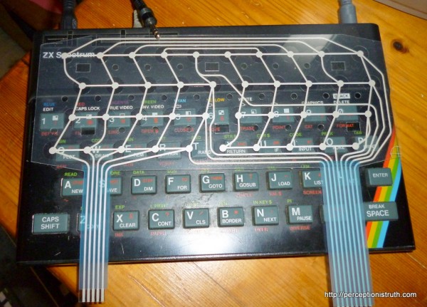
Here’s the new membrane sitting on top of the Spectrum I’m about to whack it into.  You can see why these things tear, those ribbon connectors (no edge connectors on them) stick straight into two connectors on the motherboard.

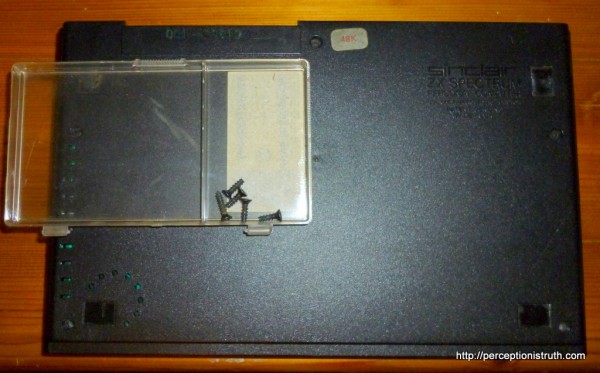
Step 1 (after taking photos) – take out the screws and keep them somewhere safe.

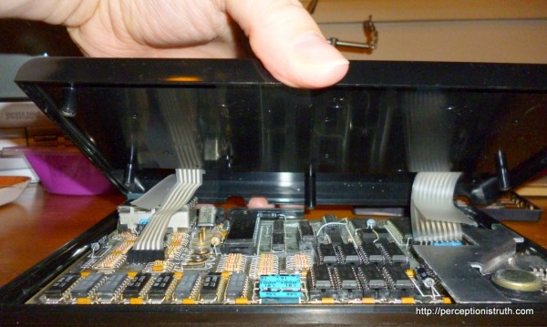
Step 2 – take off the top of the Spectrum.  Be careful when you do this, because assuming your keyboard membrane isn’t currently broken, this is the best way to break it.  As you lift the case, the ribbon connectors will keep it attached to the motherboard, so you need to open it like a clam shell and carefully remove the ribbons (assuming you’re opening it for a reason other than replacing a faulty membrane).

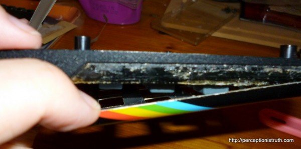
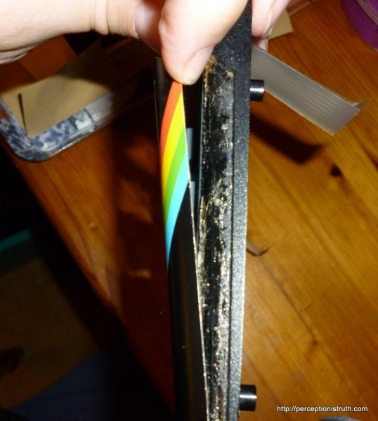
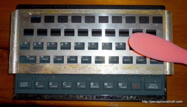
Step 3 – once you’ve disconnected the top from the bottom by removing the ribbon connectors from the motherboard, you’ll need to carefully remove the metal faceplate.  This is where you may, if you wish, resort to a heat source.  With or without one, you’re going to need a lot of patience, and I suggest something plastic and thin.  It was clear to me that someone had already had a go at this case (that’s not an original keyboard membrane).

One edge of the metal faceplate is already reasonably easy to lift.

I worked that apart with just my fingers.

However, the rest was still pretty strongly attached, so I grabbed a plastic latex spreader (don’t ask) and used the thin wedge to carefully, over the space of 10 minutes, lift the rest of the faceplate away from the case.

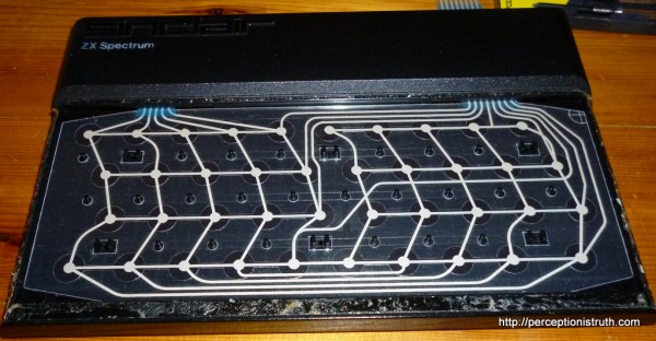
Step 4- lift off the rubber keyboard mat, remove the existing membrane, and place the new one over the plastic pillars.  The narrow ribbon strip goes on the left, the wide one on the right.  The ribbons need to go through the gap in the lid so they can enter the case.

Step 5 – With that done, replace the rubber keyboard mat.  The mat has some keying holes which sit over those 6 grippers.  If you don’t get those right, the mat will bunch up and you’ll get keys stuck under the faceplate.

Step 6 – At this stage, with the rubber mat resting on the membrane, I actually put the bottom half of the case back on, pushed (carefully) the ribbons into the connectors, and powered the Spectrum up.  I tested all of the keys, and they all worked fine.  I was so excited, I didn’t take photos.

Step 7 – put the case screws back in (gently, this is plastic)!

Step 8 – and finally, replace the faceplate.  You may or may not need to clean it and add more glue / double sided tape depending on your preference.  I was pretty confident the remaining glue would hold mine down, but if it starts to lift I can always re-glue it later.

And that’s it.  I’m really pleased it works.  A quick set of PEEK’s later and I can confirm it is indeed a 48K model with all the memory working and intact.

Thanks for the Memories

Note: This post has been altered since it was first published, to correct information about detecting the amount of memory in the ZX Spectrum, apologies for any confusion that arose as a result of the first revision of this post.


Apologies for the post title.

As I said in a previous blog, buying anything second hand, never mind 30 year old electronics, can be prone to issues.  So I went into the whole Spectrum buying thing with my eyes open, I’ve bought a lot of junk and if I end up with a reasonable Spectrum at the end of it, have had fun along the way, and maybe learned a thing or two, I’ll be very happy.

One of the issues early Spectrums had, is that the memory they used was cheap.  For a start, the 32K memory (in the 48K machines) was actually 64K chips with only half the bank of memory working.  Sinclair specifically used faulty chips to save cost.  It’s generally accepted that if the whole extra 32K wasn’t working post build, but the lower 16K was okay, Sinclair sold the machine as a 16K Spectrum (properly badged).  So you got a 16K Spectrum, but if you looked inside it would look like a 48K unit.

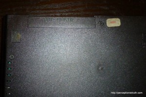
The only real way to tell was a little sticker on the outside of the case – which as you can imagine, does not stand the test of time very well.  So, people selling Spectrum’s on eBay may list them with or without memory sizes, if they’re not sure will usually say 48K, will sometimes list them as 64K for amusement, and very often the case won’t have the sticker left.

So here’s how you tell how much memory you should have, and if it’s faulty.

PRINT PEEK 23733

The return from that should be one of,

  • 255 – this Spectrum has 48K memory
  • 127 – this Spectrum has 16K memory

That 127 is the return I get on one of the Spectrums I have, which wouldn’t load Manic Miner without crashing.  If you don’t get either of those numbers, then you’ve got a problem you need to locate.  Even if you get 127, you could still have a 48K Spectrum in which the upper memory isn’t working, either as originally sold, or because it has developed a later fault.

You can also get the total memory you have, this little bit of code is all over the web (including World of Spectrum),

PRINT PEEK 23732 + 256 * PEEK 23733

That returns 32767 for a 16K Spectrum (16K ROM, 16K RAM), and 65535 for a 48K unit (16K ROM, 16K base RAM, 32K additional RAM).  If you don’t get either of those numbers, then you’ve got a memory fault of some kind, and need to do some digging.  You can check this site out for more advice on doing that.  Or, with even more detail, this page over at WoS.

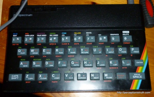
I haven’t had a chance to test these out on the ‘fully working’ model yet (because it’s not fully working, the keyboard membrane is bust) but I’m hoping it turns out to be a 48K unit, the case certainly has the 48K sticker on it (see photo above).

Over time, Spectrum motherboards get moved between cases, repairs are made, cases are replaced, stickers wear off, and even when they were new, Sinclair would make repairs under warranty that meant the serial number, sticker, case and motherboard no longer matched.  So in essence, unless you see the output from those commands, the other information like case serial number or photo’s of the motherboard is still only a best guess at the actual configuration you’re going to get!

The Mystery of the Missing Video Signal

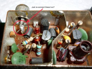
Now that I have a TV I don’t mind putting at risk, I thought it was about time to try seeing what kind of signal I can get from the Spectrum +2.  This is the one where it appears the RF connection has been severed, but the composite mod doesn’t appear to have been done either.  I asked around on Usenet and Twitter, and got various pieces of advice for both fixing the RF and testing Composite.  Folk on Usenet suggested just soldering the connection back from the orange capacitor to the RF socket,

however, Gareth Halfacree responded on Twitter, and pointed out he thought there was a 47ohm resistor missing.  Judging by those photo’s, the capacitor solders back into the PCB, along with the 47ohm resistor, and it is the resistor which ultimately connects to the RF socket.

Gareth was kind enough to take a few DSLR shots of the modulator in his ZX81 to help me diagnose where the connections should go.

So, this isn’t going to be as simple as I first thought.  I do have some options, I could pick up a 47ohm resistor and have a go at patching it up myself (which, considering I’ve never soldered a device to a PCB in my entire life should be an exciting challenge), I could get a complete modulator from an otherwise non-working Spectrum and replace it (they’re pretty generic), or I could just use a composite output and forget about the RF.

The advice from Usenet is that you can just touch the end of a phono lead to the composite input, while touching the shielding to the modulator case (which is grounded), and that’ll test whether or not the composite feed is viable.  So I took the +2 apart again, and had a go at that.  Nada, zip, just a solid black screen with some flickering white lines.

Of course, that doesn’t mean it’s not working, it might mean I’m just an idiot, or completely inexperienced and missing something obvious.  However, I had a TV I didn’t mind blowing up, some solder, some phono leads I wasn’t emotionally attached to and a desire to ‘mess about’.  I also happen to know the Spectrum 128 +2 has an 8 pin DIN connector on the back, which is used for video (RGB), but it also includes a composite output on pin 1 with ground on pin 2.  You can read all about this here, although I originally found it in this PDF (not sure which is the original source).  Before I go any further, this is the Grey +2 model – the Black +2A model has a very different pin-out on the 8 pin socket, and pin 1 is actually +12V.

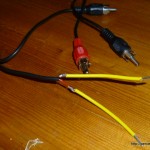
So, some hackery and flux sniffing later, and I had a ‘test cable’.  I guess you can all laugh at my soldering now.  If I’d been doing this for a while I guess I’d have some connectors rather than trying to solder wire to wire, but there you go.  The wire in the phono cable is pretty fine, so rather than try and just stick it into the DIN socket, I soldered some more manageable pieces onto the end.

Now, holding the signal wire in pin 1 and the ground in pin 2 – I can finally get a composite output on the TV.  It’s not brilliant, it’s very snowy, with brief flashes of solid picture depending on the position of the two wires, but it gives me some confidence that my next plan might work.  I’ve ordered some 8 pin DIN plugs, some phono plugs and some 4-core wire, and I’m gonna make me a cable.

I could have a shot at making the SCART cable in the documents linked above, because the TV does have a SCART input.  However,

  1. my main TV doesn’t have SCART but it does support straight composite.  So if I want to use this on the main TV it’ll have to be phono only anyway.
  2. the SCART wiring is more complex, and considering I’ve never made a cable in my life, I want to have a go at making a simple two-wire cable first.

I still have plans for fixing the UHF modulator as well, I think you can just remove the whole unit (after de-soldering the +5V and composite input), and I may use that to further practice my soldering butchery.

The Spectrums, they’re breeding

One of the advantages of taking out the Articles thing (see here), is that I can stop worrying about posting these blog entries in order.  I’ve already written two posts which are scheduled to go tomorrow and Wednesday, but another Spectrum arrived this morning.  If I’d stuck with the article structure, I would have had to either schedule this post for Thursday, or renumber the other articles.

Instead, I can share with you my joy, the joy of my lucky wife, and the joy of the postman, and announce that this arrived!

What could it be!?  Turns out it’s the first Spectrum I bought, way back on the 6th September (not going to be a positive feedback experience on eBay dude).

The good news is, it’s in pretty good condition, it’s supposed to be a 48K Spectrum and the memory test indicates it is! Yay!

That takes the total so far to 5 ZX Spectrums.  Four rubber key (16K and 48K) and one Spectrum +2.  The good news is, that at best, there’s only two more on the way (one in good condition for a Buy Now price I couldn’t ignore, and the other is broken, but I want a complete UHF modulator to play with).

At least I haven’t bought an Interface 1 or Microdrive yet.

Or an Atari 400.

Or a mint condition ZX80 for about £100.

I’ve asked about a bit on advice for taking photo’s from CRT televisions, so hopefully at some point in the next few days I’ll get some half decent shots of one of working.

Articles and Sorting

Hmm, the 8bit Mid-life Crisis posts are increasing in number pretty quickly, and I think they’re going to break the ‘articles’ page.  They already break the sorting which is alphabetical, so 10 comes before 2, and if I keep writing them at 1 a day, which is where I am at the moment, it’s going to outgrow that list of articles very quickly indeed.

That whole articles page was really a way of tying together a small number of posts on a particular topic, but I guess if I end up writing 10’s of posts for the Spectrum stuff, it’s not going to fit.  Also, frankly, it’s a ball ache adding the custom fields which make the posts show up on that page.

So, I need to have a think and approach this in a different way.  Maybe a simple 8bit Mid-life Crisis category would suffice.  I tend to under-use the categories, and they do list the posts in reverse time order so that might work out okay.

Edit: Right, stuck with ‘Retro Computing’ category, which I’ll post all the Spectrum posts under.  If you want to read them all, they’re there.  You can also read a summary of all the kit, on the Retro Computing page.