 Some people spend a lot of time when they’re young making things. I spent quite a lot of time unmaking things, but I never got around to putting them back together again. I melted plastic solders, burned airfix aircraft (after building them to be fair), took apart a radio that I remember, and generally ended up with a lot of parts. By the time I left school and went to University I was heavily into writing software and understanding computers, but not electronics. As I’ve said, one of the main reasons for getting some old Spectrums is to give myself a reason to do some electronics and electrical stuff. If you don’t have a reason to do something, then learning how to do it can be very dry, and for me, doing is learning. One thing I’m terrible at, however, is keeping at something if I don’t immediately get useful results.
I think if you were to describe me in two words it would be easily discouraged. I have so many half started DIY projects in the house; sort out lighting, cupboards, plumbing, etc. As soon as it gets hard or as soon as my first attempt doesn’t work, I’m likely to give up. With the Spectrums I’m trying hard to get over that and to do something even if I fail the first few times. We’ll see how that works out.
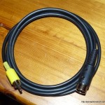
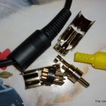 So anyway, the 128K ZX Spectrum +2 with the broken UHF modulator still has a broken UHF modulator. I tried messing with a bastardised phono lead to see if I could get composite on the TV, and I got enough of a signal to give me some confidence it was being generated. On the back of that, I bought some cable, a couple of 8 pin DIN plugs and a couple of phono plugs (photo right). I knew I’d need at least two of each because I was bound the screw up the first attempt. The phono plugs are the cheap ‘no soldering required’ type, which is good, but the connection won’t last long I should imagine.
The DIN plugs however always need soldering. After I got the plugs, I read up on how you solder them. Er, maybe I should have picked something a little easier to start with? Too late now. One of the major problems people report with cheap DIN plugs (and these are cheap) is that heating the pins to tin them, or to get the wire in, can melt the plastic. I already had some metal crocodile clips to use as heat-sinks for heat sensitive soldering, so I was hoping they would be good enough to draw the heat away from the plastic. I bought shielded 4-core wire, just because I knew this cable might be temporary and once I cut the ends off, I might want it for something else. The first decision was, do I use 1 wire for ground and 1 for the signal, or do I use the shielding for ground, and just 1 wire for the signal? I dunno, I’ve never done this before – I took a gamble and decided to use the shielding for ground.
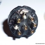
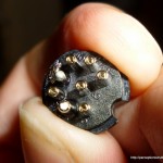
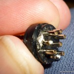
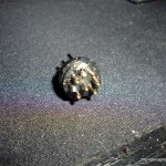
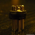
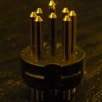
The first job was to tin the signal wire and the shielding (twisted together), and that went pretty well (so well, I took no photos). But then it was on to the DIN plug itself. Firstly, the pins are very close together so actually gripping them with the crocodile clip proved difficult. On top of that, my hands are a bit shaky these days, and I’m nothing like confident with the soldering iron. The result? One melted DIN plug connector.
The last two shots show the main issue. Pushing on the signal pin to heat it up before tinning it, it heats up the plastic, and then just slides forward. Not to mention catching the plastic with the soldering iron once (hence the splodge of solder on it). Despite this mess, it did slightly increase my confidence, the ground pin (#2) worked quite well when I got a good grip with the crocodile clip. Given that, and a deep breath, I took a shot at the second plug.
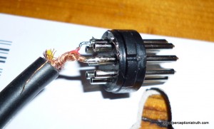
And it worked. Feeding the wires into the pins, and soldering them, is pretty fricking tricky, but this is the end result.
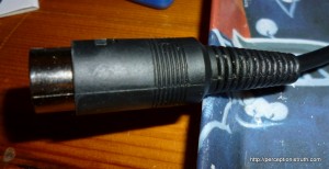
There’s too much wire on show for the signal wire, but hey, not bad for my second ever attempt. With the sheath on, and clamped into place you can’t tell anyway!
I quickly tinned the other end, and screwed / clamped the wires into the phono plug and then checked the result on the portable TV. It was a little bit disappointing, there’s definitely a signal, but it’s very snowy and loses sync every now and then. Still, it’s better than it was when I was just pushing wires into the DIN socket.
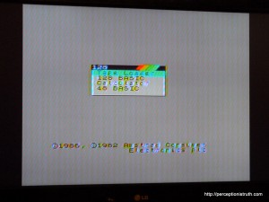
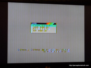
Now that I was happy it wasn’t going to blow the TV up, I tried it on the LCD in the lounge. Perhaps the portable’s composite input has issues I thought. Here’s the result.
It looks a tiny bit better on the photo than it does on the TV itself, probably because it’s a little bit blurry, but I’m bloody happy! The Spectrum +2 composite output is notoriously noisy.
Many of you may laugh when you read this – all I did was solder two wires and turn a couple of screws, but for me, this is a pretty major achievement. I wasn’t put off when the first plug failed, and I’ve got a cable that actually does what I wanted it to do (first picture in article, top right). It’s 37 years too late, but I think I may have finally made something my dad would have been proud of.
As I said, the composite on the +2 is terrible, and one of the reasons is because a transistor on the board is mounted the wrong way around. You can read all about it in this pdf or the word document linked to in this blog post. So, on the assumption that my dodgy cable is fine, I’m going to have a shot at removing the transistor and putting it back the other way around, and see if that improves the signal. Having never, in my life, soldered anything onto a PCB, this can only be a simple operation without any risk, can’t it?

