 I wanted to have a look inside the ZX Spectrum +2, to see if I could work out why the TV image is so fuzzy from the RF feed. I couldn’t see if the connector was rusty or if there was some other issue, and I’d never seen the inside of a +2 either (I never originally owned one).
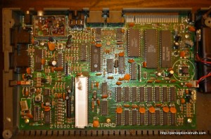
This is the second Spectrum I’ve bought where someone has replaced a missing screw with a wood screw! This time, the wood screw is about 3 times the diameter of the screw it replaced! Anyway, I got the screws out, and lifted the case apart, you have to sort of jiggle the tape deck PCB out from underneath a metal bracket, but it wasn’t too hard. The inside of the thing is pretty manky (the 48k I got along with this smelled a bit like chip fat). 20 minutes later I had the board cleaned.
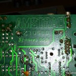
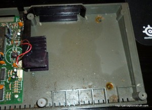 The area next to the board which sits under the tape deck looks like it’s got a bit of grease knocking around, probably from the deck itself, so I gave that a good clean as well. The back of the main board isn’t like a 48K Spectrum, so you don’t get an issue number or anything, but I took a photo just in case it means something and I need to look it up later.
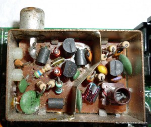
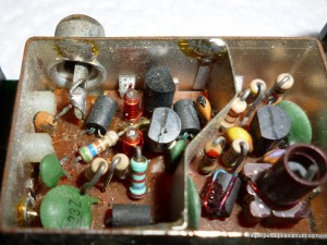
However, the main reason for taking this thing apart was checking out the RF signal. The connector itself is pretty clean, but the metal box with the RF circuitry is missing the lid, and I think I found the problem with the signal. These two photo’s are near identical, but with just a slight angle difference to help see the problem.
Is it me, or has someone cut / snipped / broken the wire attaching the RF connector to the rest of the electronics? The wire sticking up out of the orange component on the middle left doesn’t go anywhere, and the wire coming out the back of the actual RF socket isn’t attached to anything. It’s almost as if someone tried the composite video hack, and either failed or then removed it.
Essentially, I think it’s a miracle I can see anything at all using the RF feed. I need to do some more research in case I’m missing something obvious, but I can’t see how it would work at all without a connection. I don’t have a connector for the RGB out (or indeed, anything I could view it with initially), so I may get to try out my soldering skills on fixing this if I can find a diagram showing how it should look!

