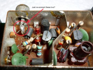
Now that I have a TV I don’t mind putting at risk, I thought it was about time to try seeing what kind of signal I can get from the Spectrum +2. This is the one where it appears the RF connection has been severed, but the composite mod doesn’t appear to have been done either. I asked around on Usenet and Twitter, and got various pieces of advice for both fixing the RF and testing Composite. Folk on Usenet suggested just soldering the connection back from the orange capacitor to the RF socket,
however, Gareth Halfacree responded on Twitter, and pointed out he thought there was a 47ohm resistor missing. Judging by those photo’s, the capacitor solders back into the PCB, along with the 47ohm resistor, and it is the resistor which ultimately connects to the RF socket.
Gareth was kind enough to take a few DSLR shots of the modulator in his ZX81 to help me diagnose where the connections should go.
So, this isn’t going to be as simple as I first thought. I do have some options, I could pick up a 47ohm resistor and have a go at patching it up myself (which, considering I’ve never soldered a device to a PCB in my entire life should be an exciting challenge), I could get a complete modulator from an otherwise non-working Spectrum and replace it (they’re pretty generic), or I could just use a composite output and forget about the RF.
The advice from Usenet is that you can just touch the end of a phono lead to the composite input, while touching the shielding to the modulator case (which is grounded), and that’ll test whether or not the composite feed is viable. So I took the +2 apart again, and had a go at that. Nada, zip, just a solid black screen with some flickering white lines.
Of course, that doesn’t mean it’s not working, it might mean I’m just an idiot, or completely inexperienced and missing something obvious. However, I had a TV I didn’t mind blowing up, some solder, some phono leads I wasn’t emotionally attached to and a desire to ‘mess about’. I also happen to know the Spectrum 128 +2 has an 8 pin DIN connector on the back, which is used for video (RGB), but it also includes a composite output on pin 1 with ground on pin 2. You can read all about this here, although I originally found it in this PDF (not sure which is the original source). Before I go any further, this is the Grey +2 model – the Black +2A model has a very different pin-out on the 8 pin socket, and pin 1 is actually +12V.
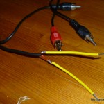
 So, some hackery and flux sniffing later, and I had a ‘test cable’. I guess you can all laugh at my soldering now. If I’d been doing this for a while I guess I’d have some connectors rather than trying to solder wire to wire, but there you go. The wire in the phono cable is pretty fine, so rather than try and just stick it into the DIN socket, I soldered some more manageable pieces onto the end.
Now, holding the signal wire in pin 1 and the ground in pin 2 – I can finally get a composite output on the TV. It’s not brilliant, it’s very snowy, with brief flashes of solid picture depending on the position of the two wires, but it gives me some confidence that my next plan might work. I’ve ordered some 8 pin DIN plugs, some phono plugs and some 4-core wire, and I’m gonna make me a cable.
I could have a shot at making the SCART cable in the documents linked above, because the TV does have a SCART input. However,
- my main TV doesn’t have SCART but it does support straight composite. So if I want to use this on the main TV it’ll have to be phono only anyway.
- the SCART wiring is more complex, and considering I’ve never made a cable in my life, I want to have a go at making a simple two-wire cable first.
I still have plans for fixing the UHF modulator as well, I think you can just remove the whole unit (after de-soldering the +5V and composite input), and I may use that to further practice my soldering butchery.

